Research on the benefits of using combined reinforcement with fiberglass reinforcing bars (ASC) in reinforced concrete beams
Research on the benefits of using combined reinforcement with fiberglass reinforcing bars (ASC) in reinforced concrete beams
Abstract
One of the main problems hindering the introduction of composite reinforcing bars into construction practice is their low modulus of elasticity and the absence of a yield plateau. To analyze the application of combined reinforcement, several design reinforcement options were considered. As the diameter of the steel reinforcement located in the tensile zone of the beam was reduced, the required cross-section of fiberglass reinforcement was determined while maintaining the load-bearing capacity. Based on the results obtained, it is concluded that the use of combined reinforcement is advisable, as its introduction into reinforced concrete beams leads to a significant reduction in weight and economic benefits.
1. Introduction
At present, reinforced concrete structures represent the most dominant and commonly applied material in the construction of industrial and civil facilities. This composite system unites the compressive strength of concrete with the ductility of steel reinforcement, functioning as a monolithic unit. Within such a system, concrete primarily absorbs compressive loads, while reinforcing bars are responsible for resisting tensile and bending stresses. Traditionally, reinforcement is arranged in areas subjected to the highest tensile forces, which ensures an increase in the bearing capacity and overall reliability of the structural element. In recent decades, however, engineering practice has increasingly relied on prestressing methods. Such techniques substantially improve the tensile and flexural resistance of concrete, which, in turn, enhances the overall stability and service life of the structure.
According to the requirements of GOST 31938-2012, composite reinforcement (CR) with a periodic profile is defined as a load-bearing rod with a uniformly distributed anchoring relief oriented at an angle to its longitudinal axis. It is manufactured from thermosetting resin, continuous reinforcing fibers, and additional fillers. Different periodic profiles of CR are intended to ensure the necessary bond strength between the reinforcing bar and the surrounding concrete matrix. Polymer-based reinforcement exists in several main forms: GFRP (glass-fiber reinforced polymer with helical ribbing), BFRP (basalt-fiber reinforced polymer with longitudinal ribbing), CFRP (carbon-fiber reinforced polymer), and AAF (aramid-fiber reinforcement with transverse ribbing). In all these cases, the fiber material is impregnated with a polymeric binder, most often epoxy resin. Following impregnation, the bars are transferred to a specialized thermal chamber for curing. After the drying cycle, the finished product acquires its final mechanical characteristics and becomes suitable for application. Among the listed options, GFRP and BFRP have gained the widest acceptance in practice. Figure 1 illustrates their behavior under load compared to conventional steel reinforcement.
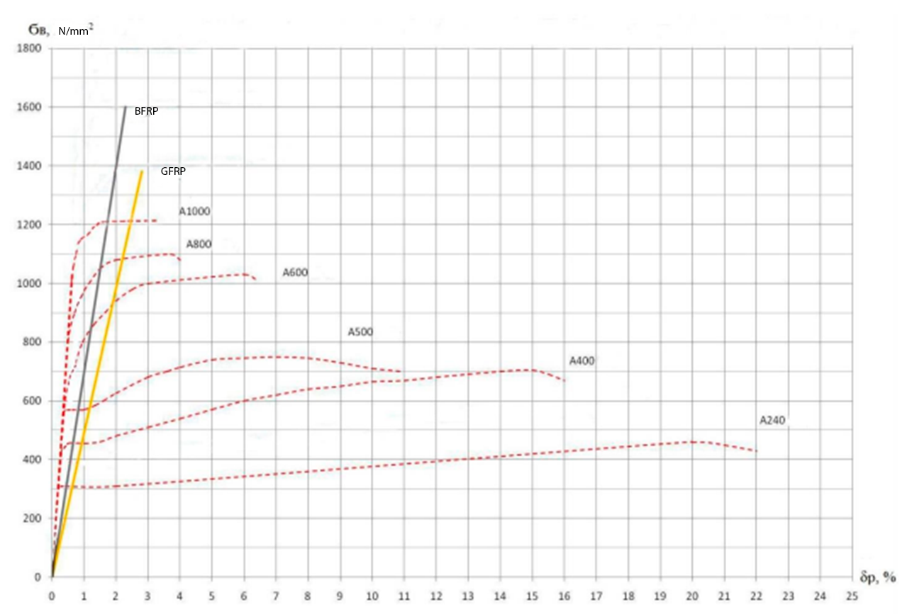
Figure 1 - Strength diagram of various types of reinforcement
Considering the specific features of composite reinforcement, it can be concluded that its use is justified in a broad range of construction projects. The most effective applications include:
- reinforcement of monolithic and precast concrete elements, as well as in combination with steel bars;
- structures exposed to aggressive media that accelerate corrosion of steel (e.g., chloride salts, high concentrations of industrial gases, etc.);
- components of road infrastructure subjected to de-icing agents;
- rehabilitation of reinforced concrete structures damaged by corrosive environments;
- thin-walled elements where standard protective concrete cover cannot be achieved (e.g., noise barriers, fences, architectural panels, and other similar products);
- bridge structures, where piers are in constant contact with water and deck slabs are regularly exposed to de-icing chemicals;
- specialized facilities such as MRI rooms in hospitals, where non-magnetic materials are required
;- complex-shaped building components where steel reinforcement is difficult to install;
- structural systems requiring built-in monitoring capabilities.
Despite the listed advantages, composite bars also exhibit notable limitations. The most critical drawbacks hindering their large-scale adoption are their relatively low modulus of elasticity and the absence of a yield plateau
, . When fiberglass reinforcement is employed as the main reinforcement in the tensile zone of flexural concrete elements, it typically results in brittle failure. This is primarily due to its increased deformability and the formation of wide cracks at the early stages of loading.One of the most effective approaches to mitigating the risk of brittle failure in reinforced concrete elements with non-metallic reinforcement is the use of prestressing techniques
, , , . A number of experimental studies on flexural members with prestressed composite bars have demonstrated that the practical efficiency of such reinforcement is largely determined by the ability to apply initial tension. The relatively low modulus of elasticity remains the primary limitation preventing its widespread adoption and the complete substitution of steel reinforcement.At the same time, existing design methods developed for flexural reinforced concrete structures with steel reinforcement can be applied to composite-reinforced members, though adjustments are necessary to account for the specific mechanical properties of polymer bars. It has been shown that the theoretical strength of concrete members with full composite reinforcement often significantly exceeds the experimentally obtained values. This discrepancy highlights the need for refining current design provisions for normal section strength.
A complete replacement of steel bars with composite reinforcement, without the use of prestressing, is currently not feasible. Moreover, prestressing composite bars requires reliable anchorage systems and advanced manufacturing technologies to ensure structural integrity. To date, these technological solutions have not been sufficiently developed, which hinders the widespread use of prestressed flexural reinforced concrete members in construction practice.
At the same time, it should be emphasized that corrosion of steel reinforcement remains one of the major factors contributing to the deterioration of reinforced concrete structures over their service life. As a result, research into alternative reinforcing materials has gained considerable attention in recent years. Owing to their favorable mechanical performance and high corrosion resistance, fiber-reinforced polymer (FRP) bars have become a subject of growing interest in the construction industry as a potential alternative to conventional steel reinforcement.
One of the promising approaches to mitigating the drawbacks of fiberglass reinforcement while retaining its advantages is the use of combined reinforcement systems. The essence of this method lies in introducing a certain proportion of conventional steel bars into the tensile zone of flexural concrete members, alongside non-metallic composite reinforcement
, , , .Experimental studies have demonstrated that this technique promotes a plastic mode of failure and provides a longer stage of plastic deformation compared to specimens reinforced exclusively with steel at an equivalent ultimate capacity
, , , . This indicates that an appropriate ratio of steel to composite reinforcement can ensure sufficient stiffness and allow for favorable redistribution of internal forces.Combined reinforcement schemes are increasingly applied in industrial and civil construction. Typically, steel bars are placed in the tensile zone, while fiberglass reinforcement is positioned in the compressive zone. Such a configuration offers several advantages:
- reduction in the overall weight of the structure;
- preservation of structural strength due to the primary load being carried by steel bars;
- mitigation of electromagnetic interference;
- improved corrosion resistance as a result of optimal placement of fiberglass reinforcement.
The economic efficiency of combined systems has also been confirmed in practice. For example, a study conducted in Omsk in 2013
demonstrated that replacing the top reinforcement of two-span continuous beams with basalt-fiber composite bars resulted in a 2.83% reduction in cost and a 25.7% decrease in labor intensity. Large-scale application of such solutions in beams and slabs could multiply this effect in building construction.Further experiments carried out in 2016
revealed that beams reinforced with fiberglass bars exhibited a different failure mechanism: cracks were mainly observed in the mid-span, corresponding to the pure bending zone. This behavior highlights the relatively low stiffness and high deformability of composite reinforcement compared to steel, which resists bending more effectively. As a result, fiberglass reinforcement cannot be regarded as the primary tensile reinforcement in concrete beams but remains suitable as supplementary reinforcement, particularly in upper reinforcement layers.In addition to the approaches discussed earlier, other reinforcement schemes have been investigated in research studies. One of the proposed methods involved introducing an additional layer of composite bars into the tensile zone while simultaneously reducing the cross-sectional area of steel reinforcement.
Experimental results indicated that beams with a two-layer arrangement of steel and fiberglass bars in the tensile zone, at a cross-sectional ratio of 50/50, exhibited a higher load-bearing capacity than reference reinforced concrete specimens. However, these specimens demonstrated reduced stiffness and lower crack resistance
. Based on further analysis, it was suggested that decreasing the proportion of fiberglass reinforcement in the tensile zone to about 30% of the total area could eliminate the negative effects of this configuration while preserving structural strength .Thus, combined reinforcement provides opportunities for optimizing both the weight and economic efficiency of reinforced concrete members without compromising their reliability. The key lies in selecting an appropriate balance between steel and non-metallic reinforcement, which has been consistently confirmed by experimental studies.
Based on the analysis presented above, the objective of this study is to examine the effectiveness of combined reinforcement in reinforced concrete beams and to identify the most advantageous configuration in terms of reducing structural weight while maintaining strength and ensuring economic feasibility.
To achieve this objective, the following tasks were established:
1. Determine the load conditions for a rectangular-section beam in a residential building.
2. Develop a mathematical model of a reinforced concrete rectangular beam subjected to the calculated loads.
3. Perform a series of calculations in which part of the steel reinforcement is replaced with GFRP bars in various arrangements, and determine the required diameters of GFRP reinforcement.
4. Analyze and evaluate the obtained results.
2. Research methods and principles
The finite element method was chosen as the research approach, and calculations were performed using the LIRA-SAPR software package, which is currently one of the most widely used structural analysis tools in Russia and CIS countries.
The study considered a beam with the following characteristics:
- length: 3 m;
- cross-section dimensions: 30 × 60 cm;
- concrete grade: B25 (heavy concrete);
- reinforcement:
- longitudinal bars — A500/GFRP,
- transverse bars — A240/GFRP;
- only bar-type longitudinal reinforcement was considered (distributed reinforcement was excluded);
- calculations were performed for both ultimate limit states (ULS) and serviceability limit states (SLS).
The permanent load consisted of the self-weight of the beam, slab, and floor system. The adopted floor structure was a 15 cm cement screed on a reinforced concrete slab with a density of 2200 kg/m³. The total load was 5.1 t/m, including the self-weight of all elements and the live load. The reference configuration (Option 1) was a beam reinforced exclusively with steel bars.
The reinforcement option obtained as a result of the calculation using exclusively steel reinforcement is taken as the reference (Option 1), with which other reinforcement options will subsequently be compared.
To analyze the application of combined reinforcement, several design reinforcement options were considered.
Since the goal of this research stage is to select the optimal ratio of steel and fiberglass reinforcement, a series of iterations were conducted. By sequentially reducing the diameter of the steel reinforcement located in the tensile zone of the beam, the required cross-section of fiberglass reinforcement was determined while maintaining the load-bearing capacity.
The considered reinforcement options for the reinforced concrete beam are presented in Figures 2–5 and include:
1. Top structural reinforcement is steel; bottom reinforcement consists of two layers: Layer 1 is made of steel reinforcement, Layer 2 is GFRP. Concrete cover — 30 mm, vertical distance between bars — 50 mm. (Reinforcement options 2 and 3).
2. Top structural reinforcement is steel; bottom reinforcement consists of two layers: Layer 1 is made of GFRP, Layer 2 is steel reinforcement. Concrete cover — 30 mm, vertical distance between bars — 50 mm. (Reinforcement option 4).
3. Top structural reinforcement is steel. Bottom reinforcement is represented by two rows: steel bars closer to the center, GFRP closer to the edges. Concrete cover — 30 mm, horizontal distance between bars – 30 mm (Reinforcement options 5 and 6).
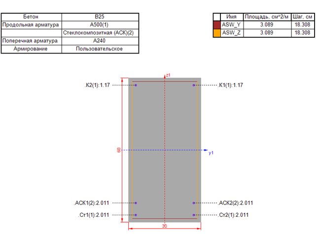
Figure 2 - Reinforcement options №2, 3
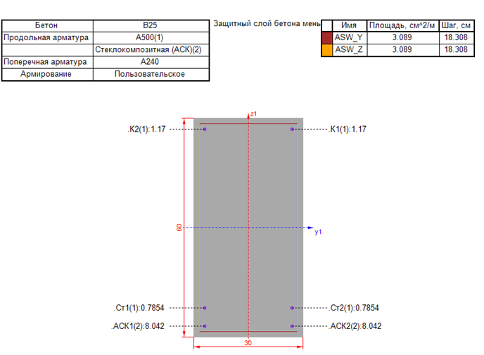
Figure 3 - Reinforcement options №4

Figure 4 - Reinforcement options №5, 6
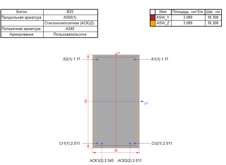
Figure 5 - Reinforcement options №7.8
Table 1 - Comparative Cost Analysis of Steel and Fiberglass Reinforcement
Reinforcement, Material | Diameter, mm | Weight per m, kg | Cost per m, RUB | Price Difference, % |
Fiberglass / Steel A-III | 6,0 / 8,0 | 0,05 / 0,395 | 9,6 / 24,79 | 257 |
Fiberglass / Steel A-III | 8,0 / 12,0 | 0,07 / 0,888 | 12,1 / 51,77 | 427 |
Fiberglass / Steel A-III | 10,0 / 14,0 | 0,12 / 1,21 | 18,8 / 67,45 | 358 |
Fiberglass / Steel A-III | 12,0 / 16,0 | 0,18 / 1,58 | 27,5 / 90,64 | 330 |
Fiberglass / Steel A-III | 14,0 / 18,0 | 0,26 / 2,00 | 44,9 / 112,27 | 250 |
Fiberglass / Steel A-III | 16,0 / 20,0 | 0,36 / 2,47 | 70,9 / 141,59 | 200 |
3. Main results
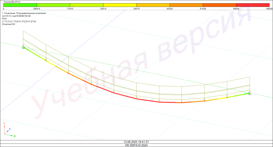
Figure 6 - Bending moment diagram
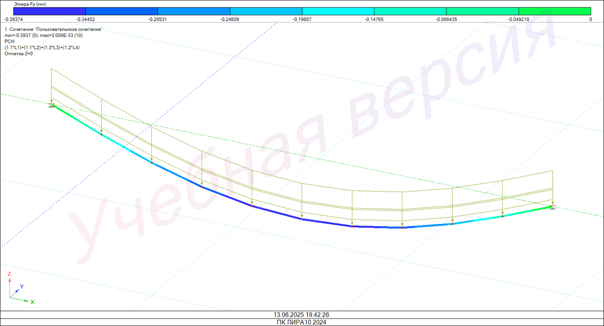
Figure 7 - Displacement diagram
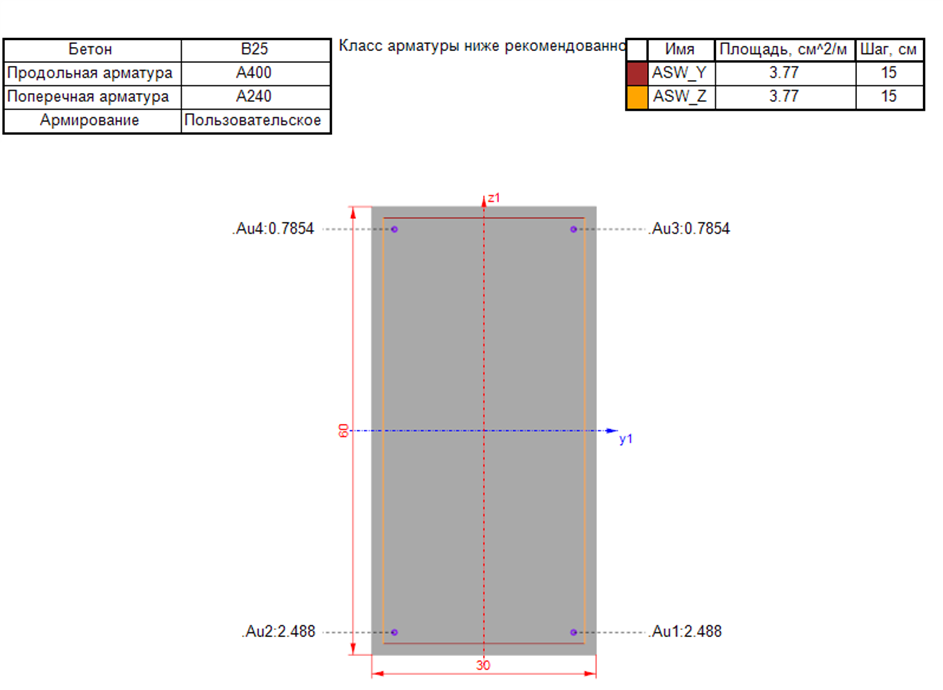
Figure 8 - Area of longitudinal reinforcement with steel
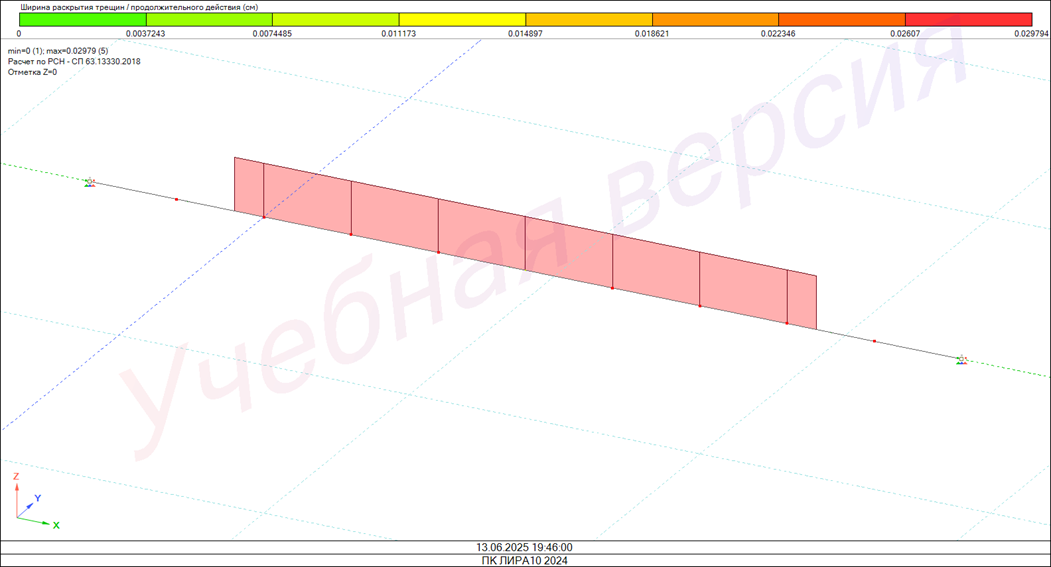
Figure 9 - Long-term crack opening width
Table 2 - Considered reinforcement options
№ | Bottom reinforcement area / Diameter (in critical section), cm² / mm | Total weight, kg | Total cost, RUB | Economic benefit, % | Weight reduction, % |
1 | 2,545/1х18 | 71,83 | 1961,29 | 0,00 | 0,00 |
2 | 2,011/1х16 2,011/1х16 | 65,61 | 2052,03 | -4,63 | 8,66 |
3 | 4,909/1х25 1,539/1х14 | 68,37 | 2120,95 | -8,14 | 4,81 |
5 | 2,545/1х18 2,011/1х16 | 68,65 | 2311,74 | -17,87 | 4,42 |
6 | 4,909/1х25 1,539/1х14 | 68,65 | 2311,74 | -17,87 | 4,42 |
7 | 2,545/1х18 2,011/1х16 | 68,41 | 2121,60 | -8,17 | 4,76 |
8 | 4,909/1х25 1,539/1х14 | 68,65 | 2311,74 | -17,87 | 4,42 |
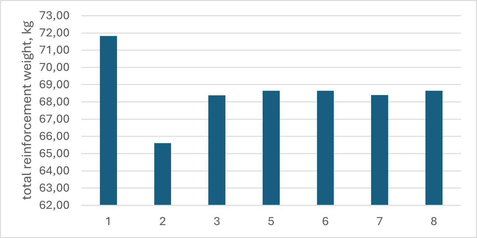
Figure 10 - Diagram of the total reinforcement weight
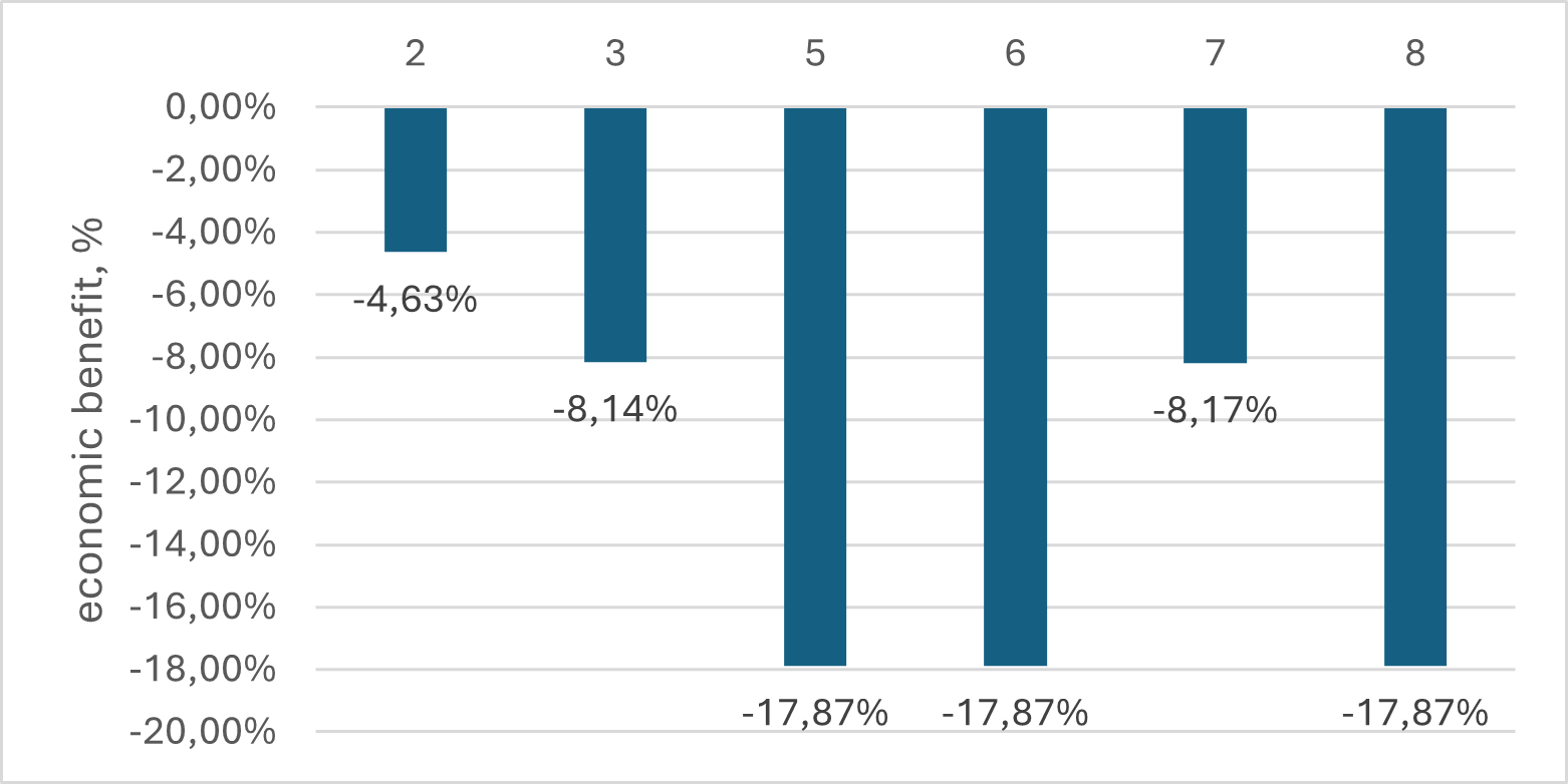
Figure 11 - Diagram of economic benefit
Table 3 - Considered modification b of reinforcement options
# | Bottom reinforcement Area / Diameter, mm (in critical section), cm² / mm | Total weight, kg | Total cost, RUB | Economic benefit, % | Weight reduction, % |
2b | 2,545/1х18 2,011/1х16 | 18,84 | 1296,95 | 33,87 | 73,77 |
3b | 4,909/1х25 1,539/1х14 | 19,44 | 1602,15 | 18,31 | 72,94 |
5b | 2,545/1х18 2,011/1х16 | 19,07 | 1347,59 | 31,29 | 73,45 |
6b | 4,909/1х25 1,539/1х14 | 19,41 | 1528,39 | 22,07 | 72,98 |
7b | 2,011/1х16 2,011/1х16 | 19,40 | 1430,33 | 27,07 | 73,00 |
8b | 4,909/1х25 1,539/1х14 | 19,32 | 1526,35 | 22,18 | 73,11 |
Based on the obtained data, a final diagram of the total reinforcement weight was compiled.
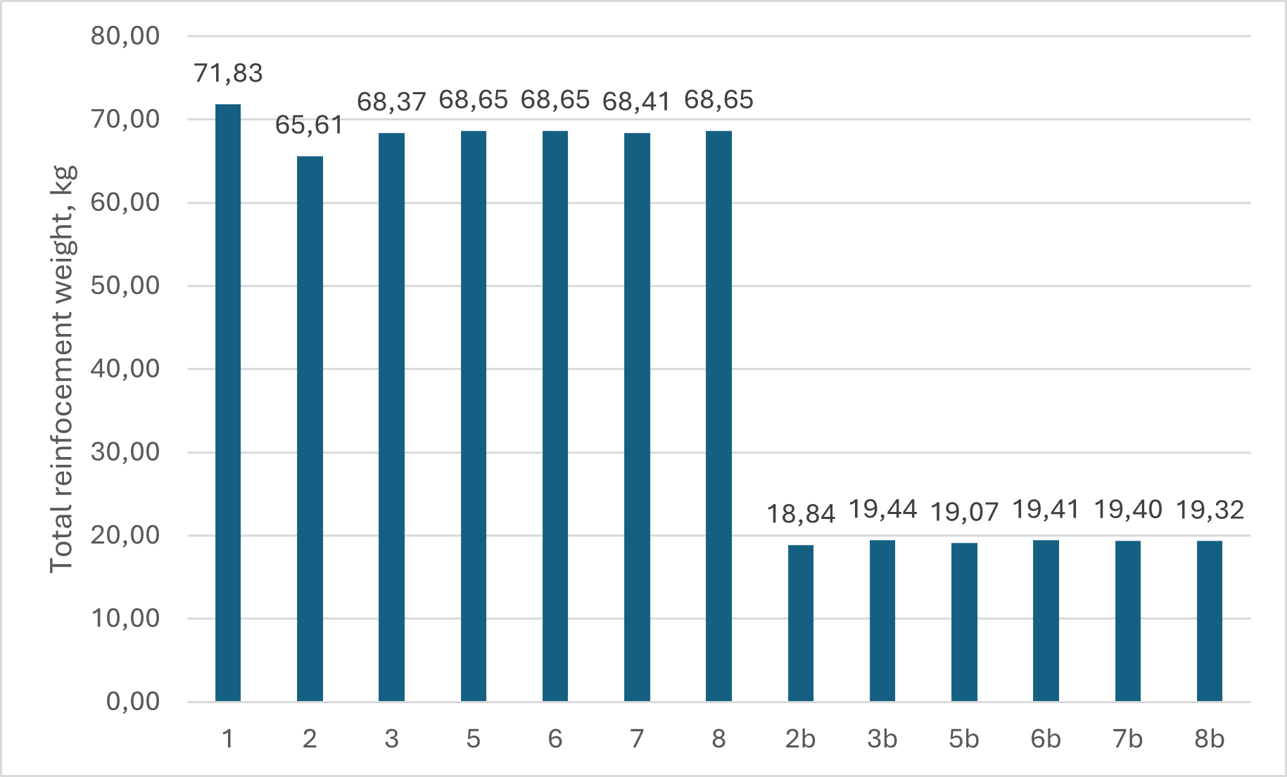
Figure 12 - Final diagram of the total reinforcement weight
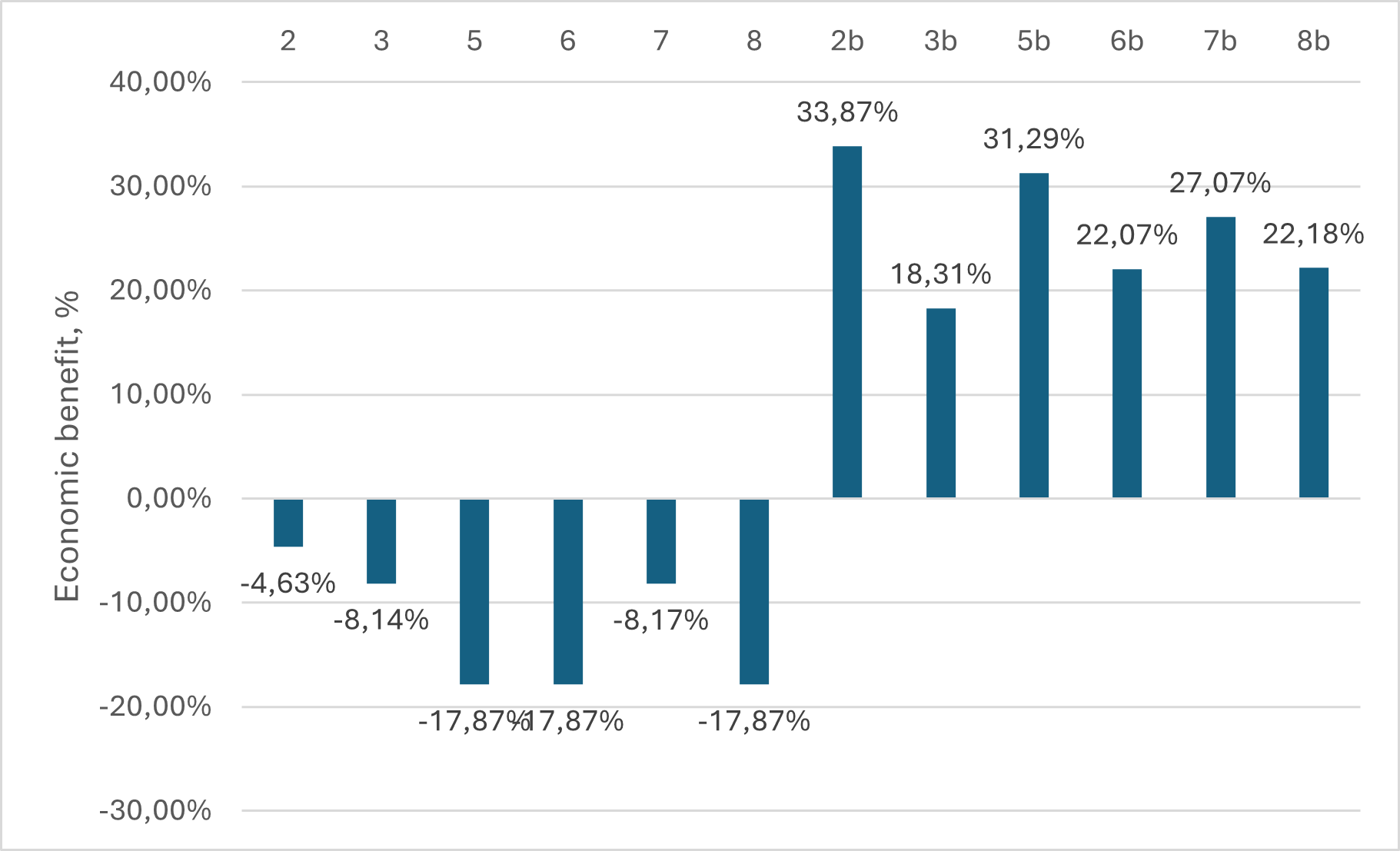
Figure 13 - Final diagram of economic benefit
Based on the comparison of the above options, it can be concluded that the replacement of transverse reinforcement has the greatest impact on the total weight of reinforcement in the beam.
Analysis of the research data allows us to conclude that modification b of reinforcement option #2 was the most beneficial. Thus, it follows that when conducting construction work using combined reinforcement, it is required: to use GFRP bars as transverse reinforcement, to use steel bars in the bottom row of longitudinal reinforcement to bear the main tensile load, and to make the second row of bottom longitudinal reinforcement from GFRP reinforcement to reduce the weight of the structure and distribute the load. Significant changes in the diameter of the steel reinforcement are not required. Reducing its diameter by one step in the assortment proves to be the most correct and economically beneficial.
4. Conclusion
The numerical analysis and evaluation of the reinforcement schemes led to several important observations. The eight considered reinforcement options exhibited significant variations in both reinforcement mass and overall cost. While certain layouts demonstrated increased load-bearing capacity, they were also associated with reduced stiffness and lower crack resistance, limiting their practical applicability in structural design.
Of particular interest were the modified options, where GFRP was introduced not only in the bottom longitudinal reinforcement but also in the top reinforcement and transverse elements. This configuration achieved the greatest reduction in structural weight — exceeding 70% — which has clear advantages in terms of transportation, handling, and installation of prefabricated elements. At the same time, the overall cost of reinforcement decreased by nearly one-third. From an economic standpoint, the long-term durability of GFRP further enhances these savings by reducing future maintenance and repair costs.
Nevertheless, it must be emphasized that excessive reduction of steel content leads to undesirable serviceability issues, such as larger deflections and wider crack openings. The optimal solution appears to be a combined configuration where steel reinforcement is concentrated in the bottom row of longitudinal bars — the zone subjected to the highest tensile stresses — while GFRP reinforcement is introduced in secondary positions to reduce weight and improve corrosion resistance.
Among the tested alternatives, Option 2b was identified as the most efficient solution. In this scheme, the top reinforcement and stirrups were fully replaced with GFRP, while the bottom reinforcement consisted of two layers: steel in the first layer and GFRP in the second. This hybrid arrangement effectively combines the strengths of both materials while mitigating their drawbacks.
In summary, the findings of this study demonstrate that hybrid reinforcement systems incorporating GFRP bars represent a promising direction for advancing reinforced concrete technology. They offer the potential to significantly extend the service life and reliability of concrete structures, particularly in aggressive environments, while simultaneously reducing structural weight and reinforcement costs. For widespread adoption, however, further development of design standards, refinement of analytical methods, and improvement of anchorage systems for composite reinforcement are essential.