ВЛИЯНИЕ ДЕФОРМАЦИИ СТЫКА НА СЕЙСМИЧЕСКИЕ ХАРАКТЕРИСТИКИ НАРУЖНОГО СТЫКА RC-БАЛОК И КОЛОНН
ВЛИЯНИЕ ДЕФОРМАЦИИ СТЫКА НА СЕЙСМИЧЕСКИЕ ХАРАКТЕРИСТИКИ НАРУЖНОГО СТЫКА RC-БАЛОК И КОЛОНН
Аннотация
Сейсмические характеристики каркасной конструкции RC в значительной степени определяются характером соединения между балкой и колонной. Когда железобетонная каркасная конструкция подвергается сейсмическому воздействию, соединение между балкой и колонной подвергается воздействию высоких напряжений сдвига. Из-за этого каркасные конструкции с усиливающим моментом RC испытывают значительные деформации при сейсмических нагрузках, что в значительной степени способствует смещению этажа, особенно в каркасных конструкциях с недостаточной сейсмической детализацией. Кроме того, при проектировании и анализе в настоящее время предполагается, что области стыка являются жесткими при моделировании, и не учитывается нелинейное поведение стыка. Следовательно, это предположение приводит к недооценке значений смещения пласта и, как следствие, к недостаточному учету сейсмического риска и неправильной оценке сейсмических характеристик сооружения. Для того чтобы точно оценить сейсмическое воздействие этих сооружений, необходимо учитывать нелинейность стержня соединения и его деформации. В этом исследовании представлен сравнительный нелинейный динамический анализ с использованием двух аналитических моделей (жестких и полужестких шарниров) с критерием разрушения при главных напряжениях. В модели для области колонны и области балки предложены пружины сдвига и пружины вращения. Характеристики пружин определяются с использованием основных напряжений в качестве критериев разрушения, основанных на принципах механики соединений. Были изучены внешние соединения балок с колоннами, чтобы понять, как они влияют на сейсмические характеристики каркасных конструкций RC на уровне узлов, а также на истерическое поведение, вызванное смещением нагрузки. Проверка экспериментальных результатов испытаний образцов, приведенных в литературе, была основана на значениях дрейфа и поведении элементов с нестандартной детализацией с использованием деформированных стержней. Результаты анализа показали, что модифицированная модель соединения может улучшить неупругие свойства образцов соединения балки с колонной, что приводит к улучшению эксплуатационных характеристик каркасных конструкций RC при воздействии сейсмических нагрузок.
1. Introduction
The area where the beam connects to the column encompasses not the joint itself but the surrounding columns, beams, and slab. These connections play a role, in determining how reinforced concrete structures behave during events as they undergo substantial deformations under seismic loads. It is crucial to design and detail these regions to prevent failure when exposed to strong earthquakes. In decades, researchers worldwide have shown interest in understanding how reinforced concrete (RC) beam column connections behave under seismic conditions. This is because they exhibit responses to forces, such as significant shear forces, diagonal tension, and high bond stresses in the reinforcement bars – all of which are prone to brittle failure. Numerous studies have demonstrated that deformations occurring at these joints significantly affect the displacement of a structure. Therefore, the seismic performance of beam to column connections has an impact, on the response of reinforced concrete frame structures.
The design philosophy of strong column-weak beam is employed in RC moment resisting frame designs to guarantee that beam plastic is generated at large displacements instead of column hinging. Consequently, the elastomeric behavior of beam-column connections is expected. However, experimental results demonstrate that even when the design philosophy is adhered to, beam-column connections undergo large inelastic deformation due to cyclic loading. This inelastic behavior significantly influences the overall behavior of the specimen and should be considered.
However, in most analyses and designs, the joint region is treated as a rigid zone, with any plastic rotations expected to take place in the beams – columns section composing the joint core, leaving the joint's inelastic behavior unaccounted for. Hence, this assumption leads to underestimating the story drift values and consequently to an improper seismic performance evaluation of the structure.
ASCE 7, AISC 341 (2010) and ACI 318 (2008) standards for special moment frames assume that the joints are rigid. However, they do not always prevent column hinging and inelastic pan zone deformation in beam to column joints. Although the new codes highlight and guide the design and detailing of joint cores better than the older codes, where most existing structures have been designed and detailed
, , .All the examples of joint failure during earthquakes referred to above demonstrate the importance of the beam-column joints in the safety of reinforced concrete construction. These findings demonstrate that the importance of the correct design of the beam-column joint core cannot be overstated.
Nonlinear displacement-based seismic assessment of reinforced concrete structures is becoming increasingly important in the nonlinear analysis of structures
, , .There are two options arising:
a) Nonlinear Static (Pushover) Analysis;
b) Nonlinear Dynamic (Time History) Analysis.
Although nonlinear static pushover analysis provides a good balance of computational effort and accuracy, the nonlinear dynamic analysis is more accurate and reliable. The methodology is based on determining the structure's nonlinear load-displacement (capacity) and curve. To capture the structure's nonlinear behavior, concentrated plastic hinges or springs are placed at critical locations. As a result, the accuracy of the capacity curve is highly dependent on the precision with which the hinge characteristics are determined. The determination of flexural, axial, and shear hinge characteristics for frame members, such as beams and columns, is well documented in the literature
, , and commercial software like (SAP2000,StaadPro 2007) can incorporate them.Many researchers have proposed and used different methods for modeling beam-column joints. Sharma et al. (2011)
proposed a novel model for predicting the joint shear behavior of poorly defined beam-column connections in reinforced concrete buildings under seismic stresses, with an emphasis on external joints. Shen et al. (2021) investigated the seismic performance of internal reinforced concrete beam-column joints using novel reinforcement details, revealing increased resistance to seismic activity. Sharma et al. (2011) provided a nonlinear seismic analysis of reinforced concrete frame structures that considers the influence of joint deformation on the structure's overall performance. Youssef and Ghobarah (2001) developed a modeling method for structural walls and beam-column couplings made of reinforced concrete, highlighting how crucial precise representation is to earthquake engineering. Celik and Ellingwood (2008) Focused on modeling beam-column joints for fragility assessment in gravity load reinforced concrete frames, emphasizing the joints' crucial role in structural vulnerability during earthquakes. Remyasri and Vijayan (2016) poposed a nonlinear seismic analysis of reinforced concrete chimneys to evaluate their performance and stability under seismic loading. El-Metwally and Chen (1988) proposed a moment and rotation model for reinforced concrete beam-column connections, which provided insight into their behavior under various loading scenarios.This study is intended to develop a lumped plasticity-based model, based on principal stress failure criterion, that can reasonably and accurately capture shear behavior and is simple to use with commercial software programs. Shear springs and rotational springs are proposed in the model for the column region and beam region. The spring characteristics are determined using the principal stresses as the failure criteria, based on joint mechanics principles. The nonlinear dynamic analysis is performed comparatively through two analytical models with rigid and semi-rigid joint assumptions within the framework of the lumped plasticity approach, using commercial software SAP2022 to validate the model.
2. Methodology
It has been noted in the preceding section that there are a number of models available in the literature for the modeling of reinforced concrete beam-column connections. Nevertheless, it is still necessary for researchers and designers to have realistic and easy-to-implement models that address the inelasticity of RC beam-column connections through general purpose programs.
The basis and formulations of a model are proposed in this section. Firstly, joint shear deformation contribution to story drift is modelled using joint mechanics’ approach. Secondly, the rigid joint is modeled using the input data of specimens. Thirdly, the semi-rigid joint model which is aimed to capture the nonlinear joint shear property is developed. To develop semi-rigid joint, model hinges are proposed. The proposed hinge characteristics are formulated for the specimens under consideration based on principal stresses failure criterion. Then, finally, the proposed model is validation is based on Experimental and analytical drifts of the specimen corresponding to the principal tensile stresses.
2.1. Joint Shear Deformation Contribution to Story Drift
The extent to which joint shear deformations contribute to story drift at the subassembly level is illustrated in Figure 1 for external joints. It can be observed that the column is subject to a slight displacement of due to joint shear deformations, with
being the beam's total depth.
This joint shear deformation can be split into two parts for the column section above the beam center line and half for the column below the beam center line, denoted by . This deformation occurs in addition to any shear deformations caused by external shear forces in the column.
Figure 1 illustrates that the beam rotates due to joint shear deformation, resulting in a beam end (point of contraflexure) displacement is
, where
is the beam tip length (in the case of structures, midpoint of a beam tip) from the face of the column. This rotation is caused only by the joint's shear deformation, and it happens additionally to any beam rotation caused by an external bending moment.
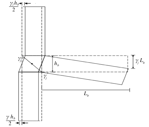
Figure 1 - Joint Shear Deformation Contribution to Story Drift of Interior joints
Non-linear springs are employed to simulate the potential inelastic behavior of the members at the critical points. The non-linearities that must be considered in the model include the members' flexural properties and shear properties, as well as the joint core's shear behavior. Concrete that has been reinforced with transverse reinforcement has been found to possess a greater degree of ductility in terms of stress-strain than that of un-reinforced concrete unconfined equivalent
, .A fiber model was generated in SAP2000 with the help of a section designer for a beam and a column section to determine the moment of rotation characteristics of a section.
The fiber model can be used to calculate the stresses and strains of each fiber based on the stress-strain functions for both confined and un-constructed concrete and reinforced steel.
This study used the Takeda multilinear plasticity model
, which is based on Takeda's model. It's a good choice because it considers the hysteresis loops that degrade and has a good mix of simplicity and accuracy. This study focused on the stress-strain properties of a reinforcement steel that was used in an uniaxial Kinematic model, with strain hardening included in the post yield part of the curve. The moment-curvature characteristics were generated from the model and consequently, moment-rotation relationship was obtained by multiplying plastic hinge length Lp of 0,5d , where d is the effective depth of the member. Theoretically, plastic hinge length is multiplied with curvature data to obtain moment-rotation relationship.Shear failure may occur in a reinforced concrete member rather than flexure failure. A reinforced concrete member's behavior at shear failure differs significantly from that of a member at flexure failure. A lack of sufficient advanced cracking causes the beam to break abruptly in shear. Hence, to obtain a complete picture of the failure, shear force-deformation characteristics must be determined in addition to moment-rotation characteristics.
In order to anticipate the characteristics of the force-deformation of the shear, the use of Trilinear Backbone Force-deformation Curves presented in accordance with the Acceptance Criteria of the American Society of Composites Engineers (ASCE) 41-13 was employed.
2.3. Modelling the effect of Joint Shear Deformation to Story Drift
Depending on how the joints deform, the best way to figure out how much joint shear affects total story drift is to use a model that takes into account the deformations in the column and the rotation of the beam caused by joint shear. As illustrated in Fig. 2, one feasible technique to model this behavior is to assign shear springs to the column area and rotational springs to the beam region.
The springs are user-defined zones of concentrated plasticity, as shown in Fig. 4, and the beam and column members are treated as frame components.
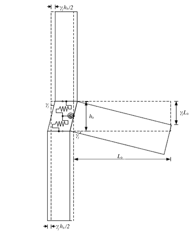
Figure 2 - Modelling of the behavior of joint deformation
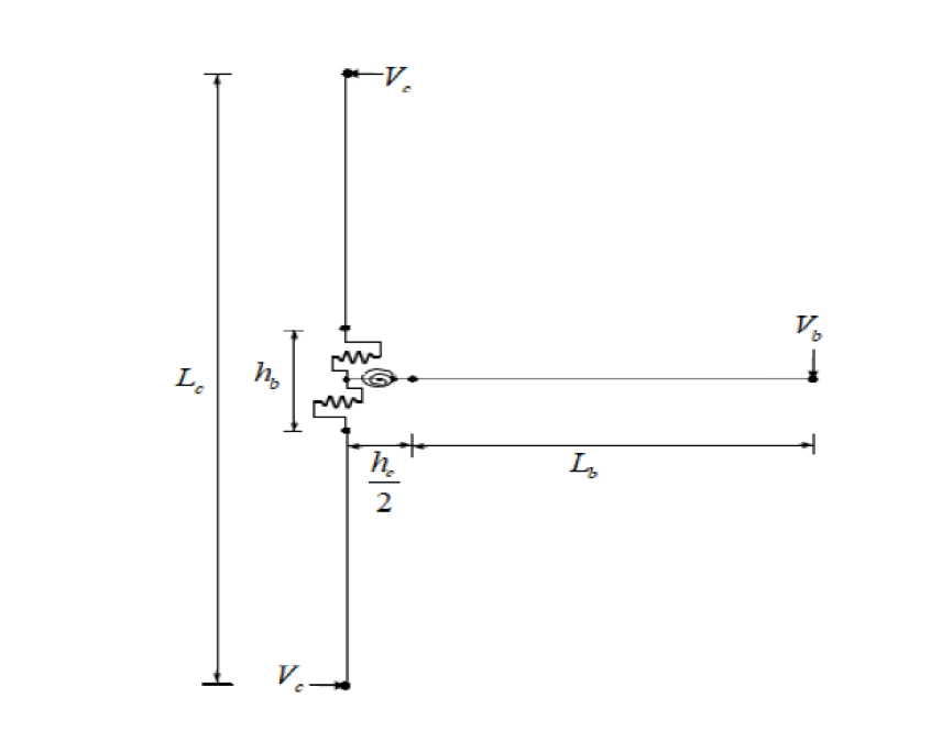
Figure 3 - Model implementation in frame elements
The springs should physically have the following characteristics: rotation of the spring, the moment in the beam, the v/s
property, joint rotation, and joint horizontal hear force
v/s
column part deformation. But since you can't model the reinforcement information directly in matrix analysis programs using frame elements, we can't measure the joint horizontal heave force.
In order to ensure that the model is suitable for use in these programs, it is necessary to define shear springs in terms of column shear forces and column part shear deformation of joints, .
To make this model suitable for use in such programs, we need to take into account the properties of shear springs such as column shear force, and column part of joint shear deformation,
.
If these joint characteristics have been determined, the model may be incorporated into the computer model of the structure to accommodate joint actions. These characteristics can be produced using the analytical computation of characteristics based on joint mechanics.
2.4. Analytical Computation of Spring Characteristics Based on Joint Mechanics
The forces acting on exterior joints because of seismic actions are depicted in Figure 4. The spring properties of the proposed joint model can be determined from plots of main tensile pressure and joint shear deformations. There are two types of joint formulations: those with no axial loading on the column and those with an axial loading of the column. However, the formulation of joint with axial load on column case will be discussed below since the column specimens selected under consideration are under axial load.
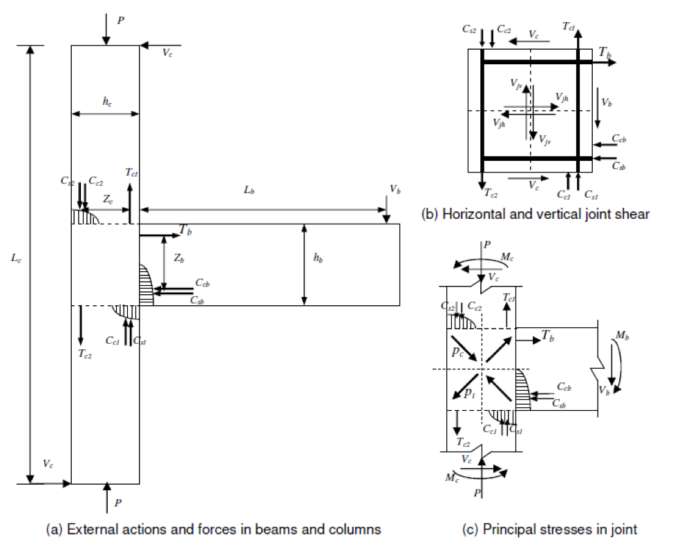
Figure 4 - Exterior joint under actions and forces
Where, and
are the vertical and horizontal joint shear stresses respectively.
Where
= the joint core breadth,
= the joint core depth,
= Vertical joint shear force,
= Horizontal joint shear force.
And, it has been shown that
, .
Hence,
Correspondingly from the above equation,
Substituting (8) into (1),
Rearranging, simplifying, and solving the eq. (9), we get,
Therefore, we can get the corresponding value of , for the given value of
,
and
.
Now, solving eq. (6) for the vertical joint shear stress, , we get,
Solving eq. (4) for the horizontal joint shear stress, , we get,
Therefore, using Eqs. (11) and (12), we can get the corresponding value of the horizontal joint shear stress, , for the given value of
.
Now, the column shear force for exterior and internal joint,
We need to use an iterative procedure get the and
values that correspond to
using this iterative method (and in turn corresponding to
), as shown in the flowchart, to derive relationships of
v/s
and
v/s
from the plot of
v/s
for the exterior joint under the axial load. The same procedure holds true for interior joints with
replaced by
.
For any given value of ,
can be calculated. Hence, for shear hinge in the column section of the joint core, we can have a
v/s
relationship, and for rotational hinge in the beam section of the joint core, we can have a
v/s
relationship.
Following the derivation of the v/s
and
v/s
relationships from given
v/s
and joint data, can be used as user defined spring characteristics in the software to model the shear behavior of the joint.
2.5. The relationship of Principal tensile stress v/s shear deformation
A number of studies have been performed in the past to measure joint shear deformation in tests
, . The plot of main tensile stress vs. shear deformation used to determine spring properties in this study is derived from Priestley (1997) . Exterior joint with beam bar bent in is under consideration as per the selected specimen. Only joints that have deformed bars as reinforcement are considered.The beam bars are bent into the exterior joint are shown in Figure 6. The joint's diagonal struts are properly stabilized. Consequently, even after assuming the first cracking to occur at , the joint will give additional resistance and therefore a hardening action until the principal tensile stress a value of
, can be considered (Priestly 1997). Following these suggestions and the experimental plots for shear deformations on the same joints
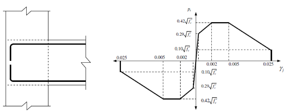
Figure 5 - The principal tensile stress-shear deformation relationship for exterior joints with bent in bars
3. Results and discussion
The analysis of exterior joint tested by researcher Clyde et al. (2000)
was performed using the formulations and assumptions given in the previous chapter. The cracked modulus was calculated to be 0,45Ec, where E is the initial modulus of concrete, calculated to be 4700(fc')0.5.The specimen is modeled by treating the connection areas as a rigid zone to illustrate the impact of treating the joint model in an RC beam to column connection. Simply put, the samples are re-analyzed without springs to model joint shear behavior.
In the upcoming sections the analytical results of the specimens are validated with their corresponding experimental results based on the load-drift/displacement hysteretic relationships.
Clyde et al. (2000)
conducted experimental cyclic loading test on the external beam-column joints with various axial loads. The joints were built in such a way that joint shear failure occurred before the beam bars yielded.There is no transverse reinforcement in the joint core. The beam longitudinal bars in the joint are not properly anchored. Figure.6 depicts the details and geometry of the joints tested. The setup of test and the cyclic loading protocol imposed into the specimen is shown in Appendix. The properties of reinforcement steel are shown in the Table 1 below.
Table 1 - Steel reinforcement strength properties
Type of the reinforcement | Bar size №, (mm) | Yield strength, Fy(MPa) | Ultimate strength, Fu(MPa) |
Beam longitudinal | №9(28,65) | 454,4 | 746,0 |
Column Longitudinal | №7(22) | 469,5 | 741,9 |
Stirrups/ties | №3(10) | 427,5 | 654,3 |
Note: source [19]
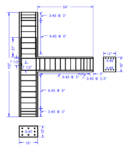
Figure 6 - Details of Exterior joint
Note: source [19]
The parameters used in the Table 3 are principal tensile stress values at the different levels i.e. ,
,
are calculated using the cylindrical concrete compressive strength and the corresponding joint rotation,
is read from the stress-shear deformation plot Figure.5. And then the following parameters are calculated corresponding to each level of principal stress using their respective expressions; vertical joint shear stress,
(eq. 3.11), vertical joint shear force,
(eq. 3.12), horizontal joint shear force,
(eq. 3.13), column shear force,
(eq. 3.14), shear deformation in the column section,
, beam shear,
(eq. 3.16), Moment in the beam,
(eq. 3.17), Tensile force in the beam
(assumed) and
(calculated), (eq. 2.2 and 2.6). The spring characteristics formulation for the exterior joint is calculated using Excel spreadsheet and tabulated as follows:
Table 2 - The geometry and material properties input data of exterior joint specimen
fc', MPa | P, KN | Lc, m | Lb, m | bc, m | hc, m | hb, m | α | σa, MPa | Cc, mm | φs, mm | φb, mm |
41 | 1380 | 2,57 | 1,27 | 0,305 | 0,457 | 0,4064 | 0,89 | 9,90 | 38,1 | 10 | 28,65 |
Note: source [19]
Table 3 - The joint springs characteristics formulation of Exterior joint specimen
Pt, MPa | γj, rad | σ, MPa | Vjv, KN | Vjh, KN | Tba, KN | Vc, KN | Δc, m | Vb, KN | Mb, KN·m | Tbc, KN |
0,00 | 0,0000 | 9,90 | 0,0 | 0,0 | 0 | 0,0 | 0,00000 | 0,0 | 0,0 | 0 |
1,86 | 0,0003 | 14,85 | 690,0 | 776,3 | 905 | 128,7 | 0,00007 | 224,5 | 285,2 | 920 |
2,69 | 0,0020 | 16,25 | 883,9 | 994,4 | 1156 | 161,6 | 0,00041 | 281,8 | 357,9 | 1155 |
2,69 | 0,0050 | 16,25 | 883,9 | 994,4 | 1156 | 161,6 | 0,00102 | 281,8 | 357,9 | 1155 |
0,64 | 0,0250 | 12,48 | 359,0 | 403,9 | 470 | 66,1 | 0,00508 | 115,3 | 146,4 | 472 |
Hence, we are able to have a v/s
and
v/s
correlations, for shear hinge in the column section of the joint and rotational hinge in the beam section of the joint, respectively.
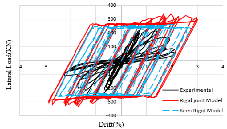
Figure 7 - Experimental and analytical results of Exterior joint
Table 4 - Summary of Experimental and analytical drifts of the specimens corresponding to the principal tensile stresses
Joint Specimen
| Principal tensile stress | Experimental | Analytical model | |||||
Rigid joint | Semi-rigid joint | |||||||
Pt,y (MPa) | Pt,u (MPa) | Drift,y (%) | Drift,u (%) | Drift,y (%) | Drift,u (%) | Drift,y (%) | Drift,u (%) | |
Exterior | 1,86 | 2,69 | 0,31 | 0,7 | 0,48 | 2 | 0,67 | 1,8 |
The above Figure 7 and Table 4 shows that the story drift is underestimated when we don't take the joint model into account. So, if we consider the joint is rigid, we will get unsafe results, but if we consider it as inelastic, we will get a good estimate of how the joint will react with a reasonable margin of error.
4. Conclusion
This research aims to develop the analytical model that characterizes RC beam-column connection’s nonlinear shear behavior under seismic loading, including joints that are inadequately and poorly detailed. The shear resisting mechanism and the joint's associated with deformational behavior were given special attention. The model is simple and easy to implement in popular commercial software for RC structure design and analysis. The model considers the actual deformational behavior of the existing beam-column connection and considers the axial load of the column because it looks at the failure criterion as being the main stress of the joint. In the report, there's detailed information about how to generate spring characteristics, which are then used to model the joint's shear behavior. The model is validated using test results, which show great consistency between the experimental and the analytical results. It's shown that the joint's shear behavior has a big impact on the sub assemblage’s behavior and, therefore, the structure. The importance of modeling the joint as semi-rigid or flexible is emphasized.